
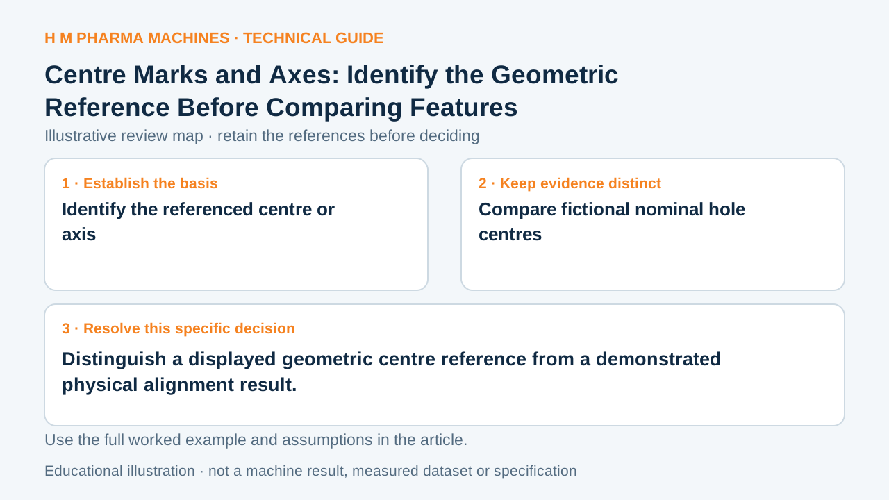
A centre reference describes geometric meaning on a drawing. It does not prove that the physical features were made or aligned correctly.
Identify the referenced centre or axis
Centre marks and centrelines provide drawing references to circular centres or axes of symmetry. Their graphical extensions help locate those references for annotation. They are not necessarily physical edges of the component. Primary reference: Autodesk: centre marks and centreline dimensioning references.
Read which geometry supplies the reference. A line can be linked to selected drawing objects or drawn as another annotation. Its visible alignment is nominal documentation and cannot establish the actual manufactured relationship without the relevant requirements and observations.
Compare fictional nominal hole centres
Imagine two circular features whose defined nominal centres lie on one axis. The drawing shows their marks on a common line, while no actual parts have been measured. The picture establishes the intended relationship in that representation, not a demonstrated physical alignment.
Changing the extension length of the centreline can make the sheet easier to read without moving the centres. This example gives no positional or coaxiality tolerance and no inspection method. It separates graphical presentation from the geometric reference and from evidence of the actual part.
Carry the reference into the real comparison
Identify the centre or axis definition used by the mating feature. Preserve its dimension origins and the relevant model relationship. Do not measure to the end of a graphical centreline extension as though that endpoint were automatically a physical feature.
If actual alignment matters to the interface, obtain the specified geometric requirement and its appropriate observation evidence. A clear nominal reference helps identify what to assess, but a visually coincident line in a PDF cannot supply the result. Keep the intended design and the actual inspection conclusion separately traceable through the handoff.
Customer Questions
Is a centreline necessarily a physical edge?
No. It can be a geometric annotation reference.
Does graphical coincidence prove actual alignment?
No. Actual parts need the required observation evidence.
Does changing an extension length necessarily move the centre?
No. It can change only the reference's display.
Primary References
These references support the technical principles discussed in this guide. The worked examples and review questions are educational.
Discuss Your Machine Requirement
Share your product, container, required output and the evidence needed for your technical review.
Request a Technical Review