
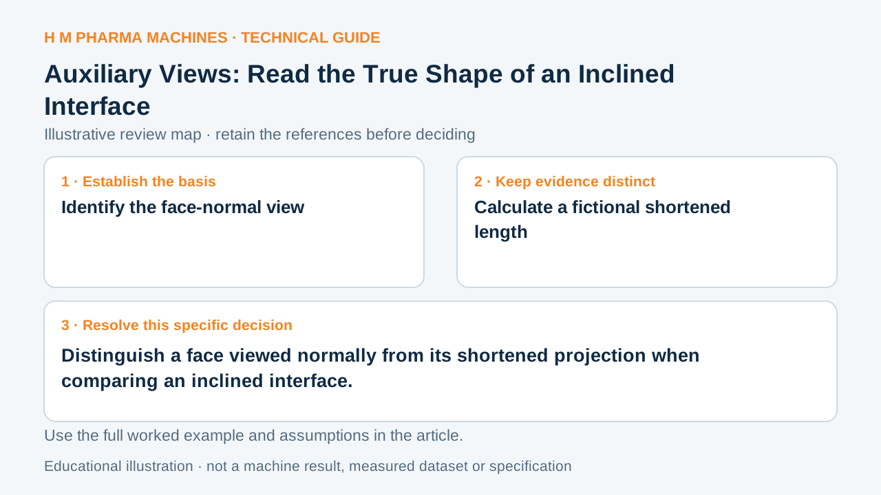
A face can appear smaller when viewed obliquely. Its projected outline and its actual geometry answer different questions.
Identify the face-normal view
An auxiliary view can present an inclined or oblique surface in a direction that reveals its true shape and size. It addresses the orientation of that surface rather than enlarging an existing oblique outline. Primary reference: Autodesk: auxiliary views of inclined and oblique surfaces.
Changing the drawing scale cannot remove geometric foreshortening. First establish whether the face is parallel to the viewing plane. Then identify which view and dimensions describe the actual interface rather than only its projected separation.
Calculate a fictional shortened length
Imagine a straight 40 mm feature tilted 60 degrees out of a stated viewing plane. Under ideal orthogonal projection, its component along that plane is 40 cos(60 degrees) = 20 mm. A page measurement of that projected component is not the original 40 mm length.
Viewing the relevant surface normally can expose the appropriate face geometry, subject to the drawing's scale and dimension meaning. The calculation is an invented geometric illustration. It is not a correction factor for an unknown drawing angle or an acceptance limit for a machine connection.
Request the view that resolves the interface
For an angled mounting face or connection, identify the face and ask which normal view carries its hole pattern and boundary dimensions. Retain the relation between that view and the assembly orientation so a receiver knows where the interface sits.
Use explicit dimensions or the applicable model definition for the required quantities. Do not enlarge a screenshot until a projected outline happens to match a catalogue value. A suitable view clarifies the nominal geometry; the actual part and agreed tolerances remain separate matters for inspection and fit review.
Customer Questions
Does enlarging an oblique view remove foreshortening?
No. Scale and viewing direction are different operations.
What is the fictional projected component?
20 mm under the stated 40 mm and 60-degree assumptions.
Should an unknown angle be guessed to correct a drawing?
No. Obtain the intended view and geometric definition.
Primary References
These references support the technical principles discussed in this guide. The worked examples and review questions are educational.
Discuss Your Machine Requirement
Share your product, container, required output and the evidence needed for your technical review.
Request a Technical Review