
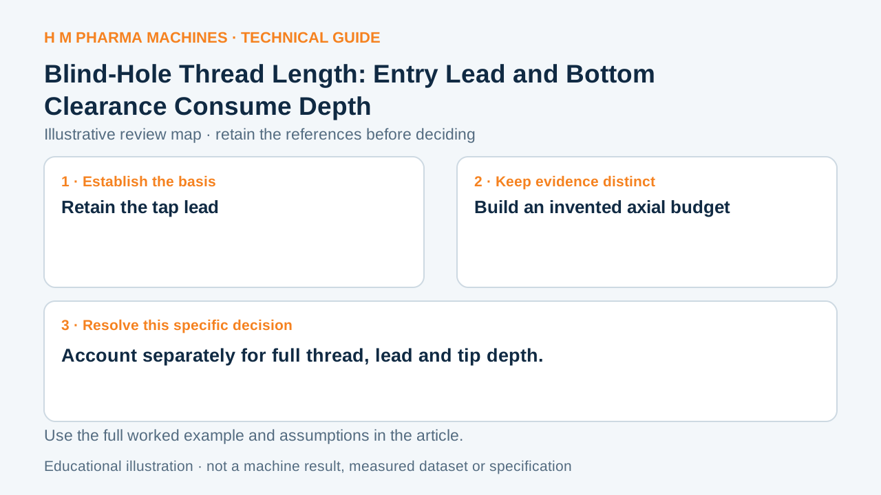
Full blind-thread length ends before the deepest drilled point.
Retain the tap lead
Gühring describes tap chamfer leads using thread counts and associates lead geometry with hole applications. The lead is distinct from the full thread form. Primary reference: Gühring tapping guide.
Build an invented axial budget
Assume a fictional required full-form thread length of 10 mm, pitch 0.8 mm, lead extending four pitches, additional clearance 1 mm and an ideal drill-point cone length of 2.4 mm. The assigned tap lead is 3.2 mm.
Under this expressly simplified axial construction, full cylindrical hole length is 10+3.2+1=14.2 mm, and deepest drill tip is 16.6 mm. This budget omits real tool-point details, chips and actual clearance requirements. It does not authorize any of the assumed allowances or constitute a machining instruction.
Draw every endpoint separately
Place the requested full-thread endpoint, lead end, cylindrical bore end and deepest drill point on one coordinate line. Identify where each allowance came from in the actual tool and component information. Do not subtract a generic chamfer count from an undocumented depth label.
Ask which endpoint the drawing actually specifies and what clearance the particular tooling requires. This makes a blind-hole review checkable without confusing full-form length with tool travel. Thread verification and machine behavior need their own evidence; a sum of invented lengths cannot establish either.
Customer Questions
What is the invented lead length?
3.2 millimeters.
Which fictional endpoint is deepest?
The drill tip at 16.6 millimeters.
Are these allowances approved values?
They are explicit teaching assumptions.
Primary References
These references support the technical principles discussed in this guide. The worked examples and review questions are educational.
Discuss Your Machine Requirement
Share your product, container, required output and the evidence needed for your technical review.
Request a Technical Review