
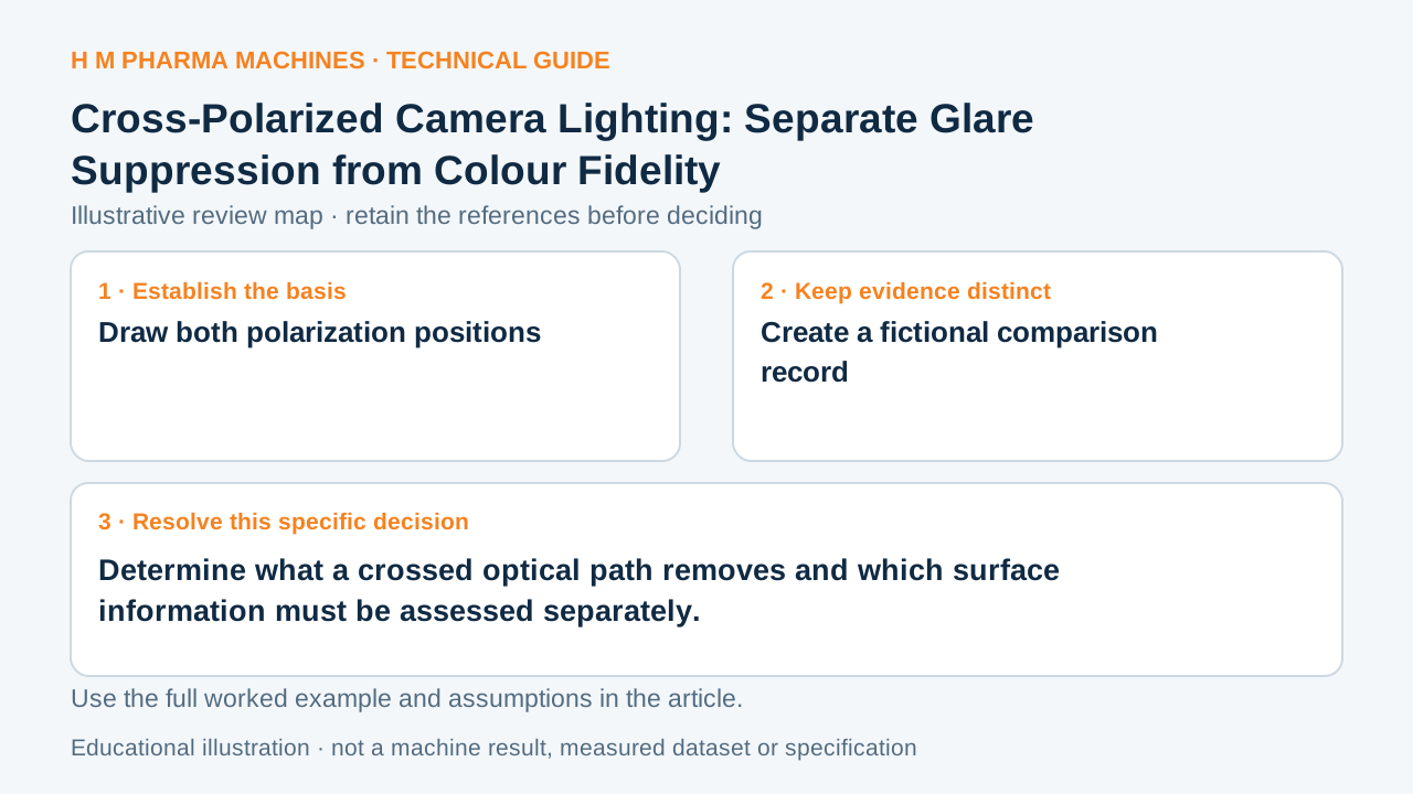
A reduced glare patch can reveal a feature, but it can also change the image signal used by another decision. Review the whole optical path.
Draw both polarization positions
Cross-polarized imaging uses a polarizer at the illumination and an analyzer at the imaging path with perpendicular axes. It can suppress suitable reflected glare components. Polarization also reduces available light, so the resulting image should be evaluated rather than described as a universal improvement. Primary reference: Edmund Optics: polarized illumination and image glare.
Identify the actual surface and the feature hidden by the reflection. A pack may contain printed paper, glossy coating and curved transparent material within the same field. The same optical arrangement need not affect those surfaces equally, and reduced glare alone does not establish colour fidelity.
Create a fictional comparison record
Imagine a label trial with a bright patch across one printed stroke. Retain an unpolarized reference, a capture with the proposed crossed path and the actual illumination state for each. Mark whether the stroke becomes observable and whether other decision features change at the same time.
Do not replace that evidence with a claimed percentage of glare removal. This scenario supplies no measured extinction, exposure recommendation or guaranteed readability. Its purpose is to expose which information the optical change preserves and which information still needs a separate comparison.
Review the trade at the decision feature
Keep polarizer orientations and the source-to-object-to-lens geometry with the approved trial images. If exposure or gain compensates for reduced signal, identify those adjustments separately. Review moving-object evidence again when exposure changes rather than assuming only the reflection was affected.
For a colour-based task, compare the specified surfaces under the final optical arrangement. For a geometry or print-presence task, inspect the relevant edge or stroke over the expected object positions. Approve the demonstrated decision evidence, with the polarization arrangement reproducible, instead of treating a cleaner-looking overall image as complete proof.
Customer Questions
Are the two axes parallel in a crossed arrangement?
No. Their intended relative orientation is perpendicular.
Does glare suppression prove colour fidelity?
No. Colour-based decisions need their own comparison evidence.
What accompanies the images?
Retain optical geometry, axis orientations and any acquisition changes.
Primary References
These references support the technical principles discussed in this guide. The worked examples and review questions are educational.
Discuss Your Machine Requirement
Share your product, container, required output and the evidence needed for your technical review.
Request a Technical Review