
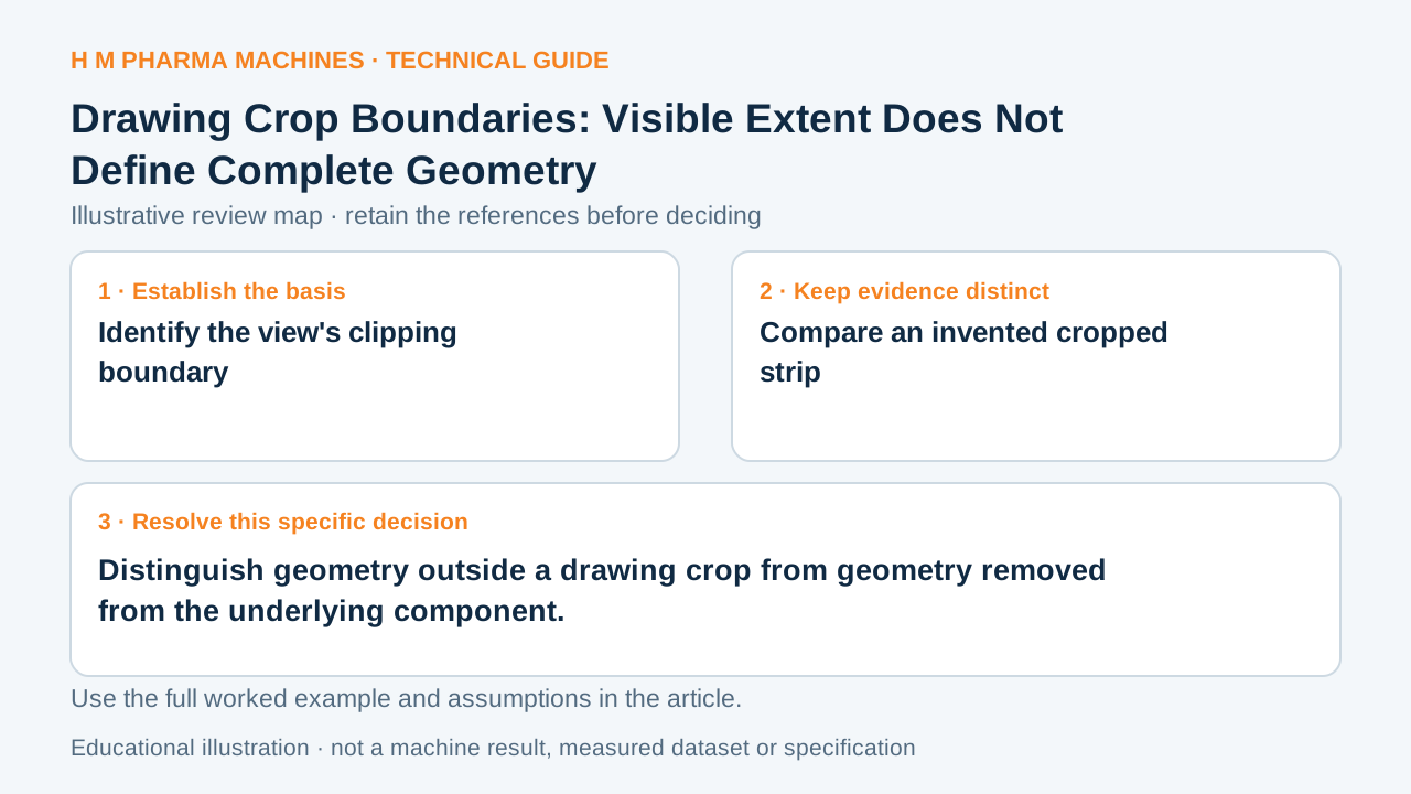
A cropped view isolates a region on the sheet. Geometry outside its display boundary can still belong to the model.
Identify the view's clipping boundary
A drawing crop clips an existing view using a defined boundary. It limits which portion is displayed rather than supplying a complete outline of the underlying component. The crop shape and the model shape are different definitions. Primary reference: Autodesk: crop boundaries that clip drawing views.
A line produced at the crop edge can be mistaken for a component's physical end. Before using the visible extent for an interface or space claim, identify whether the boundary is a display cut or an actual model edge.
Compare an invented cropped strip
Imagine a fictional 100 mm component shown in a view cropped to the model-coordinate region from x = 40 to 60 mm. Only a 20 mm interval remains visible in this simplified example. The underlying nominal component still extends beyond both displayed boundaries.
The view can be useful for discussing a local hole inside that interval, but it cannot establish the component's complete footprint. This illustration defines an ideal coordinate region, not a vendor-specific cropping workflow. It also gives no actual clearance or installation-access requirement.
Retain local and complete representations
Keep a crop identifier or surrounding reference so the receiver can locate the displayed region. Use the complete model or an uncropped view for questions that depend on total extent. Check whether dimensions and centre references still identify valid features after the clipping operation.
When an inquiry includes only a close view, state what lies outside it rather than implying an intentionally absent picture is absent geometry. A local representation can make one interface clearer while leaving other connections, projections or surrounding equipment unrepresented. The review should match the view's actual scope to the geometry needed for the decision.
Customer Questions
Does a crop boundary necessarily mark the part's end?
No. It can be only a display boundary.
What interval is visible in the fictional 40 to 60 mm crop?
20 mm of the stated 100 mm component.
Which view should establish total extent?
Use the complete model or an appropriate uncropped view.
Primary References
These references support the technical principles discussed in this guide. The worked examples and review questions are educational.
Discuss Your Machine Requirement
Share your product, container, required output and the evidence needed for your technical review.
Request a Technical Review