
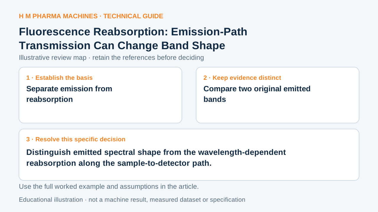
An emitted spectrum can be reshaped before detection when the sample absorbs different emitted wavelengths differently.
Separate emission from reabsorption
In an emission experiment, reabsorption of emitted radiation can produce an apparent decrease in emission yield or a distortion of band shape, an inner-filter effect. This is a propagation question: photons already emitted can be attenuated on their path through the sample before reaching the observation region or detector. Primary reference: IUPAC: inner filter effect.
A detected fluorescence curve therefore need not reproduce the underlying emitted shape unchanged. The wavelength-dependent absorption along the emission path matters. This guide focuses on that secondary reabsorption effect, separately from excitation attenuation, quenching of excited states or choosing which wavelength to scan.
Compare two original emitted bands
Define a fictional source region that emits 100 arbitrary units at wavelength A and 100 at wavelength B. Suppose the remaining sample path transmits fractions 0.5 and 0.9 at those wavelengths. The detector receives 50 and 90 units in this simplified model, changing the A-to-B ratio from 1 to approximately 0.55556.
Neither the intrinsic emission in that region nor the stipulated fluorophore amount changed between the bands. The shape difference comes from the assigned propagation factors. These invented fractions are not an absorption spectrum, an instrument response curve or a universal fluorescence-correction formula.
Keep the emission path in the shape review
Draw the excitation region, emitting region, intervening sample path and observation direction separately. Record the relevant emission wavelengths, geometry and evidence for absorption along the path. Keep detector-response corrections identified as another contribution rather than renaming every spectral distortion reabsorption.
For an actual interpretation, investigate whether the sample and measurement arrangement support an applicable correction or another method. Do not divide a real spectrum by these invented transmission factors. The worksheet asks whether a changed detected band ratio could reflect propagation rather than a changed emitter; it establishes no sample identity or analytical capability for HM.
Customer Questions
Does the fictional emitting region change its band ratio?
Its emitted ratio remains 100/100.
What does its detected ratio become?
It is 50/90 under the assumed path.
Are the invented fractions a fluorescence correction?
They only illustrate a propagation model.
Primary References
These references support the technical principles discussed in this guide. The worked examples and review questions are educational.
Discuss Your Machine Requirement
Share your product, container, required output and the evidence needed for your technical review.
Request a Technical Review