
Check the surrounding metal and mounting category before using an inductive sensor distance in a drawing.
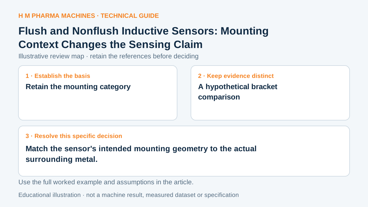
Retain the mounting category
Pepperl+Fuchs distinguishes flush and nonflush inductive constructions because surrounding metal interacts with the sensing field. A sensor distance belongs with its mounting requirements. Primary reference: inductive construction categories.
A threaded cylindrical housing does not prove that its sensing end may be buried in every metal bracket. The relevant datasheet drawing identifies what can surround that particular head. This guide reviews a drawing assumption; it gives no installation or powered adjustment procedure.
A hypothetical bracket comparison
Imagine two proposed layouts using the same intended target. Layout A leaves the stated sensing-end clearance visible; layout B adds a close metal collar around that region. Copying the detection-distance label between layouts ignores a changed boundary condition. Neither layout is judged acceptable from this sketch alone.
Make a worksheet with sensor identity, flush/nonflush designation, bracket material, surrounding geometry and the applicable drawing reference. Mark dimensions required by the supplier rather than filling missing values with a rule remembered from another sensor. Equal housing diameter does not establish equivalent field behavior.
Close the drawing question
Ask the component supplier to compare the proposed mounting geometry with the selected sensor requirements. Keep target-material evidence and electrical compatibility in separate rows so a mounting correction does not appear to settle every detection concern.
For machinery integration, retain the approved sensor-and-bracket revision with the target definition. A later guard or support added beside the head can reopen this geometry question. No particular sensor, clearance or detection capability is asserted for an HM machine.
Customer Questions
Does a threaded housing prove flush mounting?
Read the selected construction and drawing.
Is target material the same question?
It changes the target response rather than surrounding geometry.
Are universal clearance dimensions supplied here?
Use the selected sensor requirements.
Primary References
These references support the technical principles discussed in this guide. The worked examples and review questions are educational.
Discuss Your Machine Requirement
Share your product, container, required output and the evidence needed for your technical review.
Request a Technical Review