
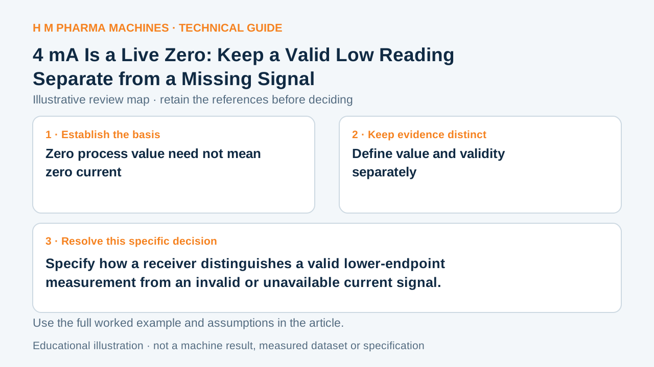
Specify how a receiver distinguishes a valid lower-endpoint measurement from an invalid or unavailable current signal.
Zero process value need not mean zero current
In a conventional linear 4–20 mA mapping, 4 mA represents the lower measurement endpoint and 20 mA the upper endpoint. TI explains that this offset provides a basis for distinguishing the measurement range from some fault conditions. A receiver should consequently avoid treating every near-zero current as a valid zero process value. The actual out-of-range and failure indications still depend on the identified transmitter, receiver and configured diagnostic policy.
TI: implementing a 4–20 mA current loop on TI DSPs supports the technical principle above.
Define value and validity separately
Make a signal table with current range, engineering-unit mapping, validity or quality state, operator display and intended machine response. Include start-up, unavailable signal and documented transmitter-failure behavior where applicable. Do not copy fault thresholds from an unrelated transmitter standard or forum post. Use the component documentation and the project's actual requirements.
A display that clamps negative or below-range values to zero can conceal a problem if quality is discarded. Record whether the HMI or data logger preserves validity separately from the numeric value. Alarm handling is an application design question: a missing level signal, for example, may need a different response from a valid low level.
Hypothetical scaling and fault worksheet
For an invented signal mapped from 0 to 10 bar, 12 mA corresponds to ((12 − 4)/16) × 10 = 5 bar. Four milliamps corresponds to the defined 0 bar endpoint. A reading of 0 mA lies outside the stated valid measurement mapping and should not simply become another valid 0 bar row. Its cause is not established by the number alone: power, wiring, input state and device behavior need investigation. Build three worksheet rows for valid endpoint, valid midrange and unavailable or invalid signal. These hypothetical readings are not a test of any HM instrument and provide no universal alarm-current threshold.
Use acceptance cases that test meaning
An interface acceptance plan should verify the documented scaling and the handling of each agreed quality state through the receiver, display and logged data. Keep those expected states separate from the procedure used by qualified personnel to produce test conditions. Do not manipulate live plant wiring to follow a general educational article. When planning process signals for a machinery project, ask for the range and diagnostic behavior together. The useful output is a clear state table that prevents an unavailable measurement from being mistaken for a reassuring process zero.
Customer Questions
Does 0 mA always identify one specific failure?
No. It is outside the conventional mapping, but the cause needs the actual architecture and diagnostic evidence.
Can the HMI show zero and retain a fault state?
It can if the design preserves quality separately; verify the agreed behavior rather than assuming it.
Should all transmitters use identical alarm-current thresholds?
Do not assume that. Use the identified device documentation and the agreed interface policy.
Related Equipment References
Review the actual offered equipment and application separately from this educational example.
Primary References
These references support the technical principles discussed in this guide. The worked examples and review questions are educational.
Discuss Your Machine Requirement
Share your product, container, required output and the evidence needed for your technical review.
Request a Technical Review