
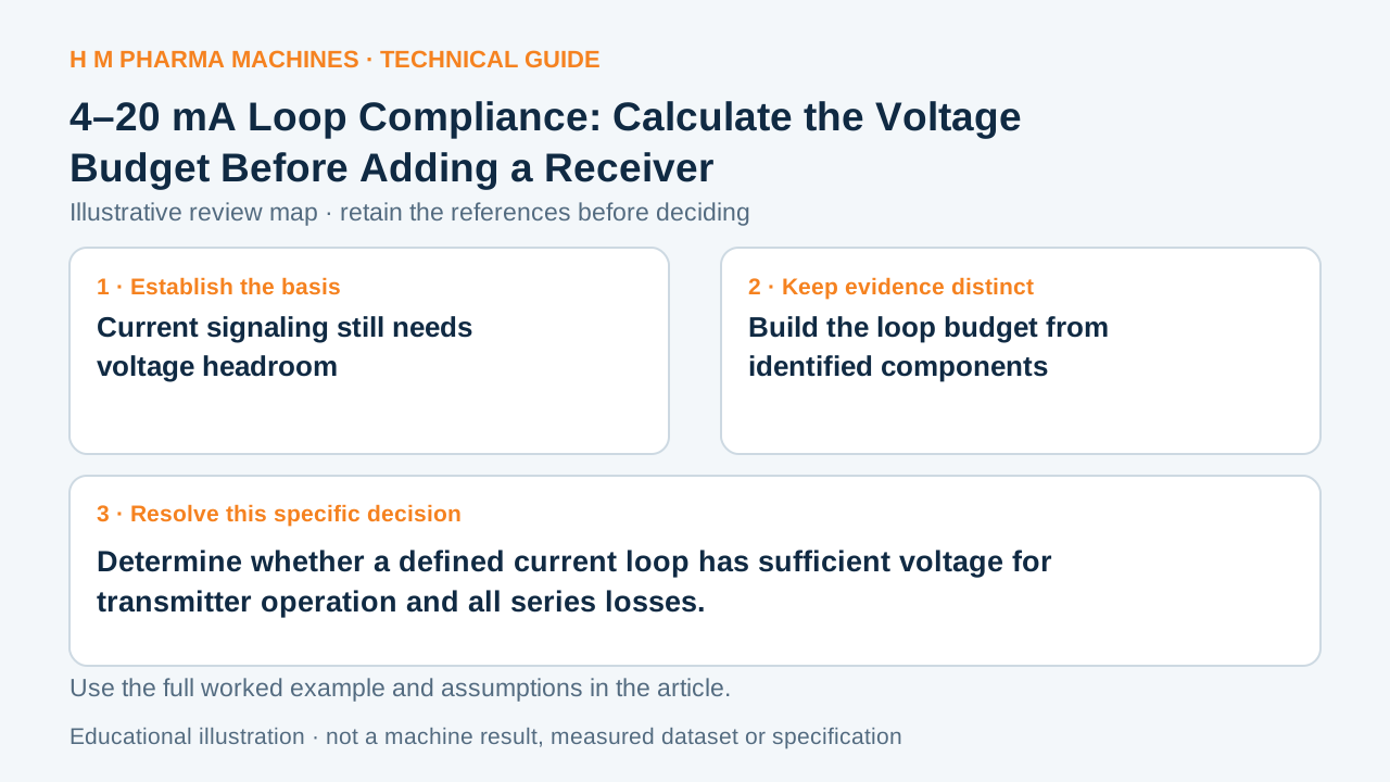
Determine whether a defined current loop has sufficient voltage for transmitter operation and all series losses.
Current signaling still needs voltage headroom
A two-wire 4–20 mA transmitter needs enough voltage to operate while the loop also develops voltage drops across its wiring and receiver loads. TI's compliance-voltage explanation makes this distinction explicit. Adding a display, isolator or receiver can therefore affect the available headroom even though the signal is current-based. A loop that seems plausible at a low current may run out of voltage nearer full scale, depending on its actual component requirements.
TI: two-wire transmitters, background and compliance voltage supports the technical principle above.
Build the loop budget from identified components
List supply voltage, the transmitter's required operating voltage and every relevant series drop. For a resistive burden, calculate voltage as current multiplied by resistance. Use the applicable current and the documented worst-case component conditions; the nominal supply label is not necessarily its minimum available value. Components with their own nonlinear or specified drops need their actual data-sheet basis.
Record wiring resistance, receiver burden, barrier or isolator drop and any other element the identified architecture includes. Keep active and passive interface assumptions explicit. This is a design-review worksheet, not permission to connect instruments according to a generic sketch. The responsible electrical designer must confirm the actual loop architecture and installation.
Hypothetical compliance calculation
Assume a fictional 24 V supply, a transmitter needing 12 V, a 250 Ω receiver and 20 Ω total wiring resistance. At 20 mA, the receiver drop is 5 V and the wiring drop is 0.4 V. The remaining margin is 24 − 12 − 5 − 0.4 = 6.6 V. If an imagined extra 400 Ω series burden is added, it consumes another 8 V at that current and the margin becomes −1.4 V. Under those assumptions, the revised budget does not meet the stated requirement. The figures identify no HM transmitter, input card, supply or wiring and are not a wiring instruction.
Preserve the calculation with its architecture
The accepted interface record should show the exact transmitter and receiver identities, supply basis and budget assumptions. A later added display or substitute input module should trigger a focused update rather than inherit an old pass statement. When discussing process measurements for a new machinery project, provide the required signal destination and interface details. The resulting budget explains one electrical feasibility question. It does not prove calibration, signal scaling, noise performance or correct alarm handling, which require their own evidence.
Customer Questions
Does current signaling eliminate cable voltage drop?
No. The supply must still cover the relevant series drops and transmitter operating requirement.
Why check the high-current condition?
Resistive drops increase with current, so a low-current observation can conceal inadequate headroom.
Does a positive budget verify the whole measurement?
No. It addresses compliance only; calibration, architecture, scaling and diagnostics remain separate.
Related Equipment References
Review the actual offered equipment and application separately from this educational example.
Primary References
These references support the technical principles discussed in this guide. The worked examples and review questions are educational.
Discuss Your Machine Requirement
Share your product, container, required output and the evidence needed for your technical review.
Request a Technical Review