
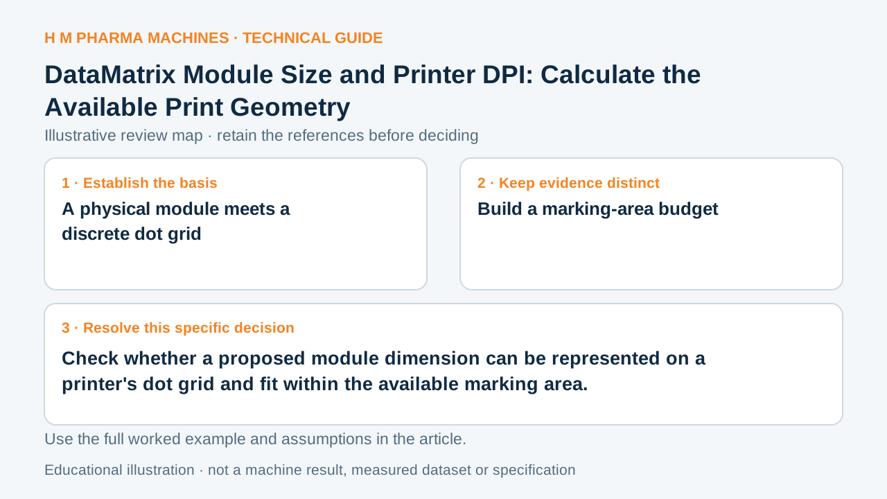
Check whether a proposed module dimension can be represented on a printer's dot grid and fit within the available marking area.
A physical module meets a discrete dot grid
GS1 DataMatrix guidance discusses module dimensions and quiet-zone context. A printer also has a finite dot spacing, so a requested physical module must be represented by a chosen number of dots. Dot resolution alone does not prove that a finished code will meet an application's requirements. It provides the geometry basis for checking a proposed layout before substrate, ink, transfer and quality evidence are evaluated.
GS1 DataMatrix guideline supports the technical principle above.
Build a marking-area budget
Record printer resolution, proposed integer dots per module, symbol width in modules and required clear surrounding space for the actual application. Calculate physical dimensions using a consistent length unit. Add artwork offsets and usable substrate area to the worksheet. The symbol's module count depends on the actual encoded data and symbol construction; do not choose it solely because a small square looks convenient.
Keep nominal dot-grid geometry separate from the printed result. Substrate behavior, printer setup and printing technology can affect edges and contrast. A geometry calculation identifies whether a layout is plausible, not whether a production symbol passes verification. Use applicable current GS1 requirements for the specific use rather than importing a dimension from an unrelated application.
Hypothetical dot and space calculation
Consider an invented 300 dpi printer. One dot has nominal spacing 25.4/300 = 0.0847 mm. Four dots per module give approximately 0.3387 mm per module. For a fictional 30-module-wide symbol with a one-module clear allowance on each side, the nominal overall width is 32 × 0.3387 = 10.84 mm. Compare that result with an imagined 12 mm usable area, and preserve the assumptions. This is a teaching space calculation, not a GS1 compliance decision, a selected symbol for a real payload or an HM printer specification. A different actual module count or required allowance changes the result.
Ask for evidence at the next layer
After confirming the proposed geometry, use the real payload and substrate to assess the actual print and its application-specific acceptance requirements. Keep the dot setting, layout and data specimen with the result so later changes are traceable. When discussing a coding project, provide the usable print area, required information and relevant application standard. Confirm the proposed printer and software capabilities. The worksheet helps avoid an impossible layout; it does not claim that a fitting symbol is readable, verified or suitable for every downstream scanner.
Customer Questions
Does high DPI alone guarantee a compliant code?
No. Geometry, data, substrate, printing and the applicable acceptance requirements all matter.
Can a module dimension use any fractional number of dots?
The implementation uses a dot grid; establish the actual rendering rule rather than assuming an arbitrary physical size.
Does fitting inside the label prove print quality?
No. A space budget and finished-code quality assessment answer different questions.
Related Equipment References
Review the actual offered equipment and application separately from this educational example.
Primary References
These references support the technical principles discussed in this guide. The worked examples and review questions are educational.
Discuss Your Machine Requirement
Share your product, container, required output and the evidence needed for your technical review.
Request a Technical Review