
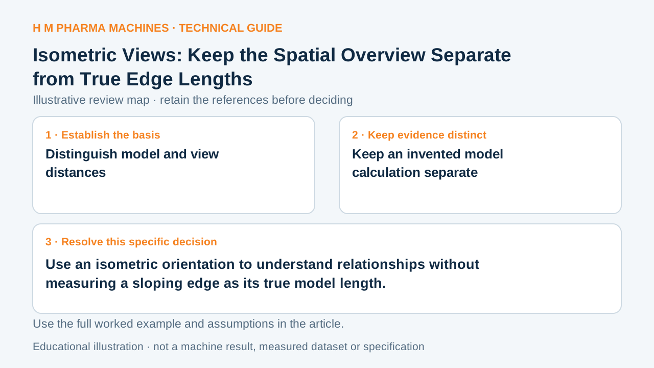
A spatial view helps explain how features relate. The visible length of an inclined segment is not automatically its true model length.
Distinguish model and view distances
Drawing systems can distinguish true dimensions derived from model geometry from measurements based on the drawing view. An isometric view presents spatial relationships, but a line's page projection does not by itself identify its true length. Primary reference: IronCAD: model-based true dimensions versus view-based measurements.
Determine what an attached dimension represents. It may refer to model geometry rather than the length obtained by putting a ruler along the projected line. The numerical annotation and the displayed segment must be interpreted through their stated basis.
Keep an invented model calculation separate
Suppose a fictional straight segment connects model points differing by 30 mm in x,40 mm in y and zero in z. Its three-dimensional length is the square root of 30 squared plus 40 squared, which is 50 mm. That model calculation does not depend on where its image is placed on the sheet.
The visible page segment depends on the projection and view scale. This example does not assign an isometric reduction factor or claim all software draws the same page length. It demonstrates why a spatial picture needs the correct geometric quantity when an interface distance is required.
Use overview and dimensional evidence together
Use the isometric representation to identify the relevant face, edge and connection. Then obtain the true quantity from the intended model dimension or an appropriate view. Preserve enough orientation information to show which features the value connects.
For machine-layout or format-part discussions, a clear spatial image can help the receiver locate a dimension without replacing its definition. If a view-based and model-based value differ, resolve the plane and dimension type before declaring the model incorrect. The review concerns nominal geometry; it supplies no manufacturing tolerance or measurement-accuracy claim.
Customer Questions
Is page line length always true model length?
No. Projection and scale affect the displayed line.
What is the fictional model segment length?
50 mm from its stated 30 and 40 mm coordinate differences.
Can the overview still be useful?
Yes. It locates features while the correct dimensional evidence supplies their quantities.
Primary References
These references support the technical principles discussed in this guide. The worked examples and review questions are educational.
Discuss Your Machine Requirement
Share your product, container, required output and the evidence needed for your technical review.
Request a Technical Review