
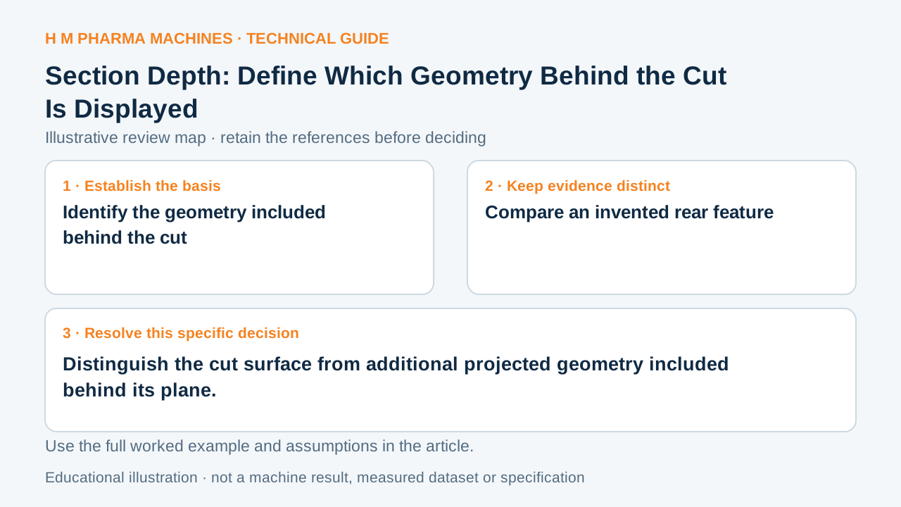
The cutting plane can stay fixed while the section picture changes. The selected display depth explains which additional geometry appears.
Identify the geometry included behind the cut
A section representation can show only geometry intersected by its cutting plane, all relevant geometry beyond it, or geometry up to a specified distance. These choices define display depth separately from the location of the cut itself. Primary reference: Autodesk: full, slice and distance-limited section depth.
A feature visible in a section can therefore belong behind the cut rather than on the cut surface. Read the intended depth interpretation before treating every outline in the picture as part of one common plane.
Compare an invented rear feature
Imagine a section taken at x = 0 in a fictional component, with a separate feature at x = 15 mm behind that plane along the stated viewing direction. A display extending 10 mm beyond the cut would not include that feature under this simplified definition; a display extending 20 mm could include it.
A slice restricted to the intersected geometry answers another question. The illustration concerns display inclusion only. It does not describe occlusion handling in every renderer, prove a real internal passage or turn a view's depth setting into a physical machining dimension.
Read cut and projected geometry separately
Identify whether the interface question concerns the cut boundary or a feature farther away. Preserve the plane position, viewing direction and display-depth definition with the image. Where multiple outlines obscure the relation, request a view that isolates the required geometry.
When two section pictures differ, compare their depth settings before concluding that the component changed. A useful released view should support the actual nominal relationship being discussed. The plane, displayed depth and dimensioned feature location provide distinct information, and all three may be needed to explain why a rear connection appears in one picture but not another.
Customer Questions
Does every visible section outline lie on the cut plane?
No. Some views include geometry behind the cut.
Is display depth the same as cutting-plane position?
No. They define different parts of the representation.
Does the fictional 10 mm depth include the 15 mm rear feature?
Not under the explicitly defined depth comparison.
Primary References
These references support the technical principles discussed in this guide. The worked examples and review questions are educational.
Discuss Your Machine Requirement
Share your product, container, required output and the evidence needed for your technical review.
Request a Technical Review