
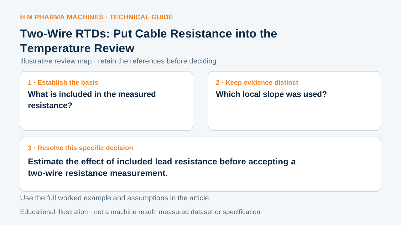
A two-wire RTD reading includes more than the sensing element. Review the complete resistance path before comparing a remote probe with a bench reading.
Identify the resistance that is measured
In a basic two-wire resistance connection, the measured voltage includes the sensing element and its series leads. Cable resistance is therefore capable of appearing as a temperature offset. The FieldPoint manual illustrates this principle; its hardware-specific wiring diagrams should not be copied to an unidentified input.
Calculate an invented local approximation
Suppose the two leads contribute 2.0 Ω in total, and a hypothetical sensor has a local resistance slope of 0.40 Ω/°C at the point of interest. Dividing 2.0 by 0.40 gives an approximate +5.0 °C indication effect. This local linear example is not a full platinum reference curve or a real cable specification.
A bench comparison using short leads can miss the installed cable contribution. Prepare two evidence columns: sensor resistance relationship and installed lead path. Preserve connector and terminal contributions where the selected input includes them.
Resolve the input arrangement before purchase
Ask the supplier which lead effects the actual input compensates, how cable resistance is constrained, and which connection alternatives are supported. Retain the installed cable description with the temperature result. Changing to another wire count requires a compatible input and the approved wiring method, not merely an extra conductor.
Primary reference: Manufacturer technical reference.
Instrument evidence worksheet
This blank worksheet is for your own project. It contains no H M machine trial result.
| Review question | Evidence to retain |
|---|---|
| What is included in the measured resistance? | Sensor, leads and connections |
| Which local slope was used? | Applicable resistance/temperature relationship |
| Which input connection is supported? | Exact model and approved diagram |
Customer Questions
Can short bench leads represent every installed cable?
No. Compare the actual resistance paths.
Is the illustrative 5 °C an RTD specification?
No. It follows only the invented resistance and local slope.
Does this guide give terminal wiring instructions?
No. Use the identified input’s approved diagram.
Primary References
These references support the technical principles discussed in this guide. The worked examples and review questions are educational.
Discuss Your Machine Requirement
Share your product, container, required output and the evidence needed for your technical review.
Request a Technical Review