
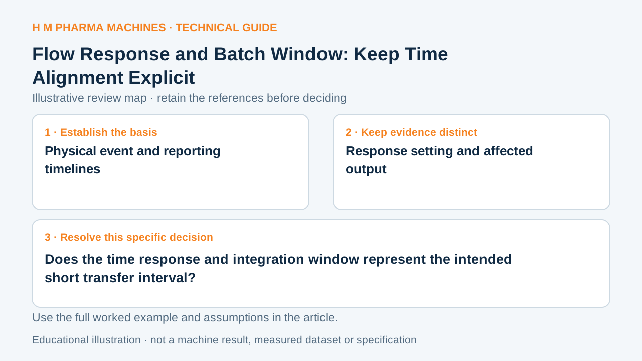
A sensor’s response setting and a controller’s batch window need a common time basis. A displayed rate is not automatically a complete short-batch total.
Identify the Physical Basis
Measuring and display response can be configurable; OMEGA’s hybrid flowmeter datasheet lists selectable response-time settings for its instrument. That establishes why response identity matters, but it does not describe every meter’s internal totalizer. A smoothed rate, native totalizer and controller-integrated rate can follow different processing paths and must be identified separately.
Work Through an Example
Consider a hypothetical two-second rectangular physical delivery at 10 mL/s, giving 20 mL. If an imagined reporting path delays that signal by one second, integrating only from the physical start to the physical end captures 10 mL; the remaining reported area appears afterward. This is a simple pure-delay illustration, not the dynamic model of OMEGA’s meter or any HM installation. It demonstrates the importance of matching windows.
Use the Result in the Review
Put physical valve or pump events, reported rate timestamps and totalizer readings on one timeline. State where the batch begins and ends for each record. Ask whether a response setting applies to the display, analog output, pulse output or totalizer. Where the controller integrates a rate, obtain its sampling and timestamp basis. Compare full-window totals before interpreting an early reading as product loss.
Use a flowmeter filling trial to verify the selected machine’s actual short-dose behaviour. This timing worksheet does not prescribe a damping value or assume changing display response changes the dosed quantity. It identifies which signal path needs evidence.
Does the time response and integration window represent the intended short transfer interval?
This blank worksheet is for your own project. It contains no H M machine trial result.
| Review field | Reference or result | Responsible person |
|---|---|---|
| Physical event and reporting timelines | To complete | To complete |
| Response setting and affected output | To complete | To complete |
| Integration start/end and timestamps | To complete | To complete |
| Native versus controller-integrated total | To complete | To complete |
Customer Questions
Does display damping necessarily alter a native totalizer?
Not necessarily. Confirm the instrument’s processing path.
Can delayed reporting resemble missing volume?
Yes, if comparison windows are not aligned.
Is the pure-delay example a meter specification?
No. It is an explicitly hypothetical timing illustration.
Related Equipment References
Review the actual offered equipment and application separately from this educational example.
Primary References
These references support the technical principles discussed in this guide. The worked examples and review questions are educational.
Discuss Your Machine Requirement
Share your product, container, required output and the evidence needed for your technical review.
Request a Technical Review