
A flowmeter’s installation evidence must match the upstream disturbances actually present. One generic straight-length number can miss the relevant geometry.
Identify the Physical Basis
Bends, valves and other upstream features can disturb the flow profile used by some measuring principles. Endress+Hauser’s vortex reference explains that required inlet runs depend on the disturbance and selected device. A model-specific allowance for a compact installation should be read with its conditions; it is not permission to apply the same layout to every meter.
Work Through an Example
Imagine a hypothetical drawing with 300 mm of clear pipe upstream of a 25 mm nominal reference size, giving 12 reference diameters. A supplier’s stated requirement of 10 diameters for one identified disturbance would be a different basis from 20 diameters for another. The drawing’s two bends in different planes cannot be replaced in the comparison by one bend merely because both routes have the same clear length.
Use the Result in the Review
Mark each upstream component, its distance and orientation on the submitted drawing. Preserve the diameter definition used by the selected manual and any conditioner identity. Ask the supplier to assess the actual arrangement rather than supplying only a total pipe length. Where a manufacturer accepts shorter runs, retain the exact selected sensor and performance conditions that support that acceptance.
In a flowmeter filler enquiry, identify the instrument principle and available installation space. This article does not assert a vortex installation or prescribe the illustrative lengths. It turns a vague space question into a reviewable profile-and-geometry comparison.
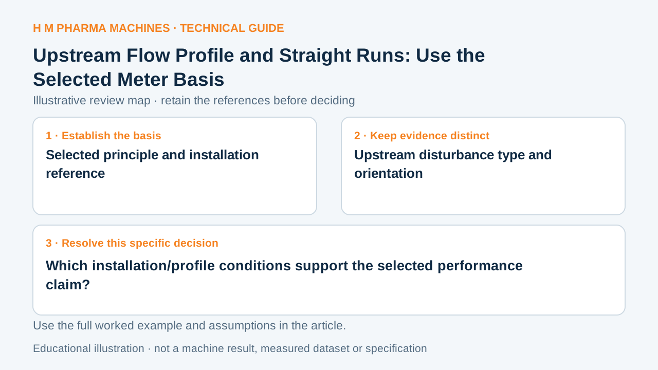
Which installation/profile conditions support the selected performance claim?
This blank worksheet is for your own project. It contains no H M machine trial result.
| Review field | Reference or result | Responsible person |
|---|---|---|
| Selected principle and installation reference | To complete | To complete |
| Upstream disturbance type and orientation | To complete | To complete |
| Distances with diameter definition | To complete | To complete |
| Conditioner or compact-layout evidence | To complete | To complete |
Customer Questions
Is physical clear length enough to assess installation?
No. Disturbance type and selected meter conditions also matter.
Can I reuse another model’s short-run claim?
Only if the selected model’s own evidence supports that layout.
Does a flow conditioner guarantee every installation?
No. Its type and applicable conditions must be defined.
Related Equipment References
Review the actual offered equipment and application separately from this educational example.
Primary References
These references support the technical principles discussed in this guide. The worked examples and review questions are educational.
Discuss Your Machine Requirement
Share your product, container, required output and the evidence needed for your technical review.
Request a Technical Review