
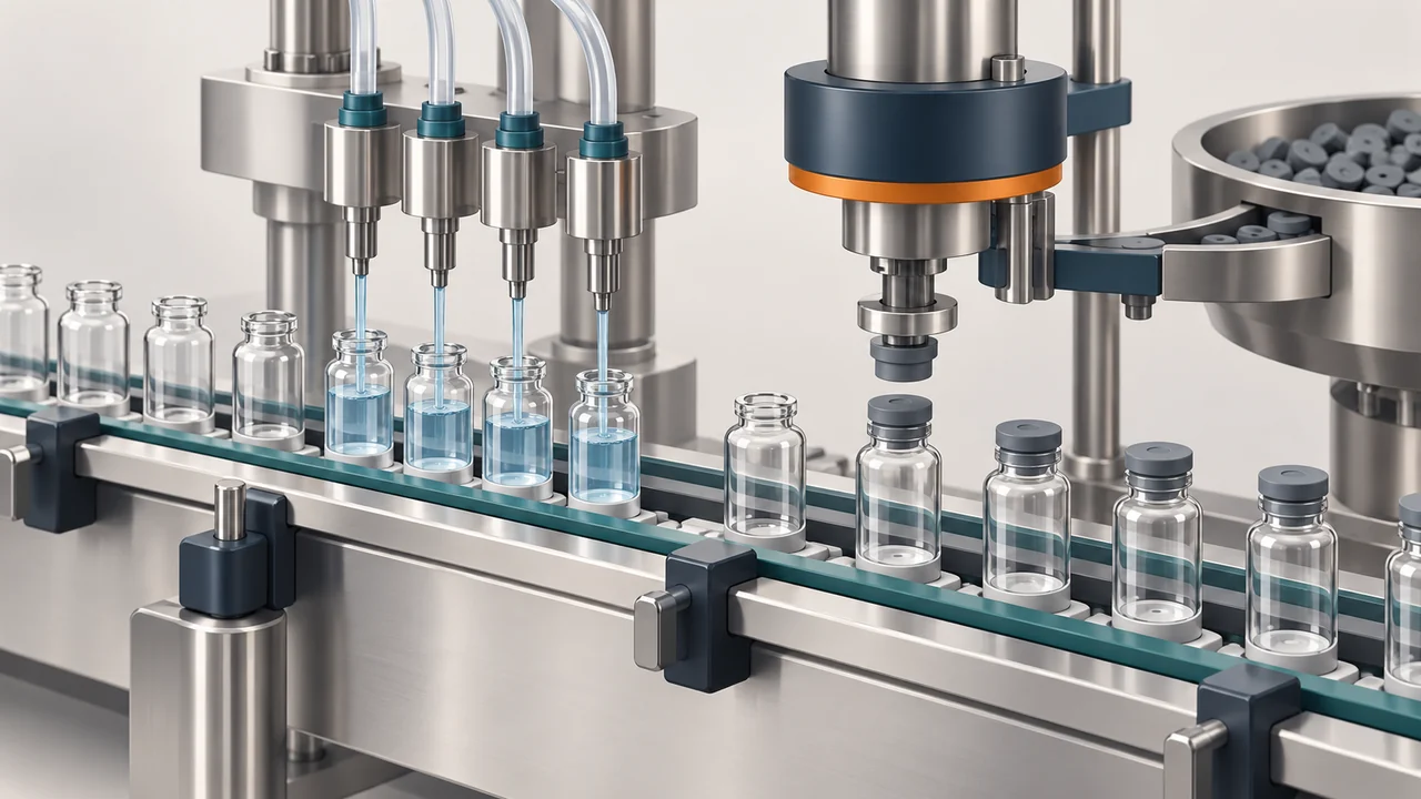
A vial filling and rubber stoppering line brings several interfaces together: the container must reach the dosing position, the stopper must arrive correctly oriented, and the closed or partially stoppered vial must leave in the condition expected by the next machine. Choosing only by nominal vial volume misses these handovers. This guide focuses on the component and line information needed to discuss a workable configuration with H M Pharma Machines.
Review the vial and stopper as a matched set. Define the filling method, required stopper seating position, container handling and downstream transfer before comparing output. Use actual components and a written trial record to check those interfaces together.
Start with a matched vial and stopper set
Two vials with the same nominal volume can have different body diameters, heights and neck finishes. A stopper feeder and insertion tool also depend on the stopper geometry, not just the vial label. Supply dimensioned drawings and representative components from the intended suppliers, including alternative formats that will be used later.
Identify component revisions and permitted dimensional variation. Keep the vial and stopper references paired in the format list so a later purchasing substitution triggers a fit review. Photographs help explain the pack, but they do not replace dimensions or physical samples.
Separate dosing choice from container presentation
The vial liquid filling stoppering machine indexes vials under the selected liquid dosing nozzles. The injectable dry powder filling rubber stoppering machine instead delivers measured powder doses before stopper insertion. Both need stable container positioning, but their product supply and dosing paths are different.
Discuss the actual liquid or powder characteristics separately from vial transport. For the liquid, consider foaming, product-contact tubing and cleaning access. For powder, describe flow behavior and the dosing conditions. Neither a suitable stopper nor reliable indexing establishes that the selected dosing arrangement meets the product acceptance criteria.
Use an interface checklist before selecting tooling
| Interface | Information to supply | What to observe |
|---|---|---|
| Vial handling | Body, base, height and neck drawings | Stable entry and consistent dosing position |
| Stopper presentation | Stopper drawing, material and samples | Correct orientation and reliable pickup |
| Insertion | Full or partial seating requirement | Consistent position without damaged components |
| Downstream handover | Next-machine layout and entry condition | Stable transfer without disturbing the stopper |
Assign each format a component identifier rather than describing it only as a small or large vial. The checklist then becomes a common reference for engineering, component purchasing and the people attending the machine trial.
Define full or partial stopper seating explicitly
The published liquid filling platform allows the specified full or partial stopper position. State which position your process needs and how it will be assessed. Partial seating is a deliberate process condition, not permission for an inconsistent or tilted stopper. The powder filling platform presents and inserts compatible rubber stoppers before transfer toward the next closure operation.
Agree the acceptable seating appearance or measurement with the component and process owners. Check whether the stopper can be displaced during outfeed. Stopper insertion and subsequent aluminum-seal crimping are separate operations; a successful insertion trial should not be treated as proof of the final closure system.
Describe both normal flow and interrupted flow
Provide the next-machine details, transfer height, operating direction and available space. Identify where vials may accumulate and what happens when downstream equipment stops. A smooth individual machine cycle can still produce unstable transfers if the connected machines disagree about when to release containers.
Define ready, stop and fault handshakes where the controls include them. Review empty-container and missing-stopper responses with the supplier; the published platforms describe no-vial filling or dosing logic, while additional inspection and rejection functions need a separate scope discussion. Ask how the line restarts after a stopper-feed interruption without sending unsuitable vials forward.
Build a trial record around the complete handover
Run the intended vial and stopper combination through dosing, insertion and outfeed, rather than demonstrating each mechanism with unrelated samples. Record the component references, machine settings, product or agreed trial material, observed seating condition and destination of any interrupted-cycle containers.
- Observe initial startup, steady feeding and recovery after a planned stop.
- Record change parts and adjustment points for each additional vial format.
- Separate dosing results, stopper-position checks and downstream closure checks in the report.
If gas flushing, barrier integration or additional inspection is required, describe its role and boundary separately. Such features are configuration choices; their presence does not replace the site process requirements or its acceptance work.
Buyer Questions
Is nominal vial volume enough to select the handling parts?
No. Supply body, height, base and neck dimensions together with physical vial and stopper samples. Containers with the same nominal volume can require different guides, indexing parts or insertion tooling.
Can a liquid filling line use partial stopper insertion?
The published liquid platform can be configured for the specified full or partial position. Define the intended process condition, seating criteria and downstream handling before selecting insertion tooling.
Does rubber stoppering complete the final closure process?
Not necessarily. A following seal or crimping operation may still be required. Review stopper placement and the final closure acceptance separately, using the actual container and component combination.
Related Machine Guides
Product References and Further Details
These primary pages describe the published machine arrangements discussed in this guide. Use the actual product and component requirements when reviewing a configuration.
Discuss Your Machine Requirement
Share your product, container or closure samples, required output, process conditions and line layout with H M Pharma Machines for a technical review.
Request a Technical Review