01
2–100 mL Vial Range
Approved vial formats are handled using dedicated pockets and change parts.

Linear vial handling through a defined internal water and air washing sequence.
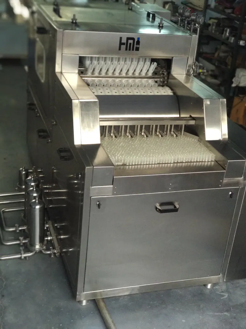
Machine overview
H M Pharma Machines manufactures the Linear Tunnel Type Vial Washing Machine in Ahmedabad, Gujarat, India. The HMLVWM series is offered for approved glass-vial formats from 2–100 mL as HMLVWM-120 (120 VPM), HMLVWM-150 (150 VPM), HMLVWM-180 (180 VPM) and HMLVWM-240 (240 VPM).
A wire-woven infeed belt transfers vials toward the infeed handling system. Mechanical cams load and unload the vials, while HDPE pockets carry them through ten internal washing positions using compressed air, recirculated water, fresh Purified Water and fresh WFI in a published reference order; the final sequence is order-specific.
Three process tanks of 40 L each and three process pumps support the process circuits; tank material, plus pump rating and contact material, are finalized in the approved order. Final output, change parts, wash configuration and tunnel interface are confirmed against the approved glass-vial sample, drawing and user requirement specification.
Machine running video
Review the reference machine demonstration, then discuss your container format and required output.
Select Play to load the video. This demonstration shows a reference configuration; final format parts, output, utilities, controls and guarding follow the approved project scope.
Available models
Choose the HMLVWM model according to the required vials-per-minute output and the approved 2–100 mL vial configuration.
Why this machine
Approved vial formats are handled using dedicated pockets and change parts.
Select HMLVWM-120, HMLVWM-150, HMLVWM-180 or HMLVWM-240 according to the required production output.
Air, RC water, PW and WFI services are shown in a published reference ten-position sequence; the final sequence is order-specific.
Product-contact parts are SS 316; tank and pump materials are finalized in the approved order.
Code 7 filter cartridges are specified; final micron ratings follow the approved process scope.
Monitoring and interlock functions are finalized in the approved control specification.
Vial handling process
The linear washing sequence coordinates vial infeed and inversion, pocket indexing, penetrating spray washing and upright discharge for downstream line transfer.
Vials are organized into the approved single- or double-track infeed arrangement using the selected turntable or feedworm interface and wire-woven transfer belt. Mechanical cams index the vials into format-specific HDPE pockets and invert them 180 degrees into a neck-down washing position.
The indexing linear-chain arrangement carries the inverted vial pockets smoothly from one washing station to the next, keeping each vial aligned with the washing positions. Track arrangement, pocket format and indexing settings are matched to the selected machine configuration and approved vial samples.
Custom spray nozzles lift mechanically to enter the mouth and neck of each inverted vial and direct the washing media into its interior. The published platform provides ten configurable internal positions using recirculated water, Purified Water, compressed air and a final Water for Injection (WFI) wash, followed by air. Nozzle travel, media pressure and the active washing sequence follow the approved process.
A final air flush reduces residual moisture before the pockets re-invert the vials into an upright, neck-up position. Mechanical cams unload the vials through the outfeed prism and pusher onto the next conveyor. Where connected to a downstream depyrogenation tunnel, transfer height, direction, conveyor capacity and line-control signals are synchronized for the agreed installation.
Reference configuration: The published model uses ten configurable internal washing positions; the exact water and air sequence is shown below. Infeed arrangement, track count, nozzle settings and downstream transfer follow the approved machine configuration. Washing prepares the vials for further processing; required sterilization or depyrogenation is specified and validated separately.
Published reference wash cycle
The following published reference sequence combines compressed air, recirculated water, fresh Purified Water and fresh WFI. The approved quotation and URS govern the final order-specific sequence.
Initial internal air stage.
First internal RC-water wash.
Second internal RC-water wash.
Air stage after the RC-water washes.
First fresh Purified Water wash.
Air stage after the first fresh-PW wash.
Second fresh Purified Water wash.
Air stage before the WFI wash.
Final internal water wash.
Final internal air stage.
Configuration note: the ten wash positions can be configured to match the approved customer washing process and user requirement specification. RC means recirculated water, PW means Purified Water and WFI means Water for Injection.
For an explanation of each washing medium and the role of air between rinses, read our vial washing cycle guide: RC Water, PW, WFI and air. Washing, sterilization and depyrogenation have separate process objectives.
External washing: any external wash stages, media and positions are finalized in the approved order and user requirement specification.
External stages, if required, are defined in the approved order.
External wash media are selected based on the approved process requirement.
Technical details
| Suitable For | Glass vials only |
|---|---|
| Output Unit | VPM — vials per minute |
| Machine Design | Stainless-steel, GMP-oriented design |
| Infeed | Wire-woven belt |
| Vial Pockets | HDPE |
| Loading / Unloading | Mechanical cams |
| Main Drive | Gearbox with AC frequency drive |
| Conveyor Drive | Gearbox |
| Outfeed | Prism and pusher toward tunnel interface |
| Frame | SS 304 |
|---|---|
| Contact Parts | SS 316 |
| Process Piping | Material, joining method and finish finalized in the approved order |
| Internal Wash Positions | 10, configurable to approved requirement |
| External Wash | Configured per approved order |
| Storage Tanks | 3 process tanks, 40 L each; material per approved order |
| Process Pumps | 3 process pumps; rating and contact material per approved order |
| WFI Monitoring | Defined in the approved control specification |
| Filter Cartridges | Code 7 type |
| Utility Pressure Response | Defined in the approved control specification |
| Cabinet Provision | Vapor-exhaust cut-out at top |
| Automation Standard | Delta PLC, 7-inch Delta HMI, Delta drive/VFD and Delta servo |
| Compressed Air | 6 bar |
| Model / Series | Published reference. HMLVWM-120 / HMLVWM-150 / HMLVWM-180 / HMLVWM-240. |
|---|---|
| Output / Throughput | Published reference. 120 / 150 / 180 / 240 vials per minute (VPM), matched to the selected model. |
| Accuracy / Acceptance Criterion | Not applicable. This is not a dosing or label-placement function; acceptance is based on stable container handling, the approved wash sequence and the FAT protocol. |
| Electrical Power | Published reference. 440 V AC, three-phase, 50 Hz; connected load 5 HP. |
| Utilities | Published reference. Compressed air at 6 bar; three process tanks of 40 L each and three pumps support the RC-water, PW and WFI cycle. Tank material and pump rating are confirmed in the approved order. |
| Overall Dimensions (L × W × H) | Overall dimensions are model- and configuration-specific. Final L × W × H is confirmed in the customer-approved GA drawing based on capacity, output, process requirements and site layout before order execution. |
| Net / Shipping Weight | Published reference. Approximately 500 kg net. |
| Capacity / Format Range | Published reference. Approved 2–100 mL vials; three process tanks of 40 L each. |
| Warranty | Published reference. 1 year; commencement, coverage and exclusions are defined in the approved order. |
| Installation / Commissioning Scope | Published reference. Installation and commissioning are available; the exact included work and customer responsibilities are defined in the approved order. |
Final model, output, wash configuration, change parts, utilities and tunnel interface are confirmed against the approved glass-vial sample, drawing and project URS.
Water consumption varies with the selected machine model, operating speed, vial size and approved washing cycle. The project-specific requirement is confirmed for the selected configuration and agreed operating conditions.
Recirculated-water flow and fresh PW/WFI consumption are specified separately during technical review.
₹15–25 lakh (INR)
Some linear washer configurations may cost up to approximately ₹25 lakh.
This is an approximate budget range. The final price is confirmed in the written quotation for the selected model, output and approved configuration.
Confirm GST, packing, freight, installation and commissioning inclusions in the written quotation.
Filtration & process supply
Three process tanks of 40 L each and three process pumps support the RC-water, PW and WFI arrangement; tank material and pump specifications are finalized in the approved order.
Code 7 cartridges are specified; final micron ratings are defined in the approved process scope.
Process-piping material, joining method and finish are finalized in the approved order.
DQ, IQ, OQ, PQ, FAT, SAT, manuals, serial-matched component certificates, wiring diagrams and machine layout can be included as defined in the approved order scope.
Process alarms & interlocks
Monitoring points, alarms and stop responses are defined in the approved control specification for the selected vial and connected line.
Vial-flow alarms and responses are defined in the approved control specification.
Required RC-water, PW, WFI and compressed-air monitoring is defined in the approved control specification.
Tank-level sensing and responses are included only as defined in the approved order.
Any required WFI monitoring is defined in the approved control specification.
Drive-overload alarms and responses are finalized in the approved electrical design.
Tunnel-interface alarms and stop logic are finalized for the approved line configuration.
Machine selection
Consider this platform when the approved vial formats suit belt, cam and HDPE-pocket handling, and the process requires ten configurable internal washing positions. The HMLVWM range provides separate 120, 150, 180 and 240 VPM models.
Preparing for the factory trial? Use our washing machine FAT checklist to agree samples, wash conditions, output checks and dispatch records.
Review the pocket format and outfeed prism and pusher together with the downstream tunnel. More washing positions alone do not establish a better cleaning result; the approved sequence and operating conditions must meet the process acceptance criteria. Compare the rotary gripper vial washing machine through the rotary versus linear selection guide.
Related machines and guide
Frequently asked questions
Answers to practical questions about vial formats, model selection, washing requirements, utilities, line integration and project documentation.
The published range covers approved 2–100 mL glass vials. Provide samples or drawings for every format so the pocket geometry, guides, change parts and handling settings can be confirmed for the actual containers.
HMLVWM-120, HMLVWM-150, HMLVWM-180 and HMLVWM-240 are rated at 120, 150, 180 and 240 vials per minute (VPM). The sustainable operating rate must be confirmed for the approved vial, washing process and connected line.
A wire-woven belt feeds vials to mechanical cams that load them into HDPE pockets and invert them 180 degrees into a neck-down washing position. The pockets are indexed through the configured washing positions. After the final air flush, the vials are returned upright and unloaded through the outfeed prism and pusher for the approved conveyor and tunnel interface.
Ten internal positions can be configured to the approved process and User Requirements Specification (URS). The published reference sequence is air, RC water, RC water, air, fresh PW, air, fresh PW, air, fresh WFI and final air. RC means recirculated water, PW means Purified Water and WFI means Water for Injection.
Any required external washing stages, media and positions are defined separately in the approved order and URS. Confirm this scope alongside the internal washing sequence.
Three process tanks of 40 L each and three process pumps support the washing system. Tank material and pump specifications are finalized in the approved order. Code 7 filter cartridges are specified; final micron ratings are defined in the approved process scope.
The published construction uses an SS 304 frame and SS 316 product-contact parts. Process-piping material, joining method and finish, and tank and pump materials, are finalized in the approved order.
Vial-flow monitoring, utility-pressure and tank-level responses, drive protection, tunnel stop logic and any required WFI monitoring are defined in the approved control specification. Confirm the required sensors, monitoring points, alarms and responses before order approval.
Review the outfeed prism and pusher arrangement with the actual tunnel, including transfer height, direction, vial format, conveyor capacity, available space and line-control signals. Final transfer and stop logic are agreed for the connected equipment.
Provide all vial samples or drawings, target VPM, required wash sequence, water and air conditions, changeover requirements, room layout, tunnel details and testing expectations. Include the required DQ, IQ, OQ, FAT, SAT, manuals, certificates and any site-specific PQ support in the document scope.
The term linear tunnel describes the washing-machine arrangement. Washing does not by itself establish sterility or depyrogenation; any required downstream sterilizing or depyrogenation equipment is specified and validated separately.
The published automation uses a Delta PLC, 7-inch Delta HMI, Delta drive/VFD and Delta servo. A 1-year warranty is listed. Installation and commissioning are available, with coverage, commencement and included work defined in the approved order.
Contact us
Contact H M Pharma Machines for model selection, wash-process review, technical discussion and quotation.